Building motion actuators and stages from scratch forces designers to order, inventory, and assemble hundreds of parts. It also increases time to market and requires technicians and specialized production equipment. An alternative is to order preengineered motion devices.
Stages and actuators are often just items on a machine’s bill of materials. If they deliver the right force, payload, positioning, and speed, machine builders don’t need to spend time giving them extra consideration. But companies can actually improve their machines by using preengineered stages and actuators.
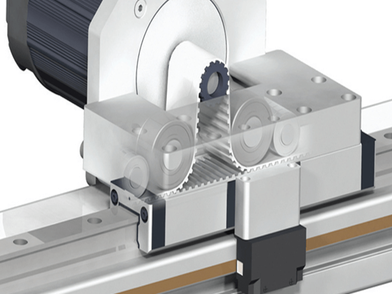
Preengineered stages like this ServoBelt linear actuator typically cost 25 to 50% less than their component-based counterparts, thanks to reduced part counts, especially of brackets and connectors. They also slash costs related to design and maintaining inventories.
Properly preengineered motion subsystems fit within a defined physical space and tie into the machine’s controls. They typically accept commands from a top-level computer interface, control card, or PLC. The simplest preengineered systems consist of little more than an actuator and connectors. Complex preengineered stages add controls and even end effectors to move payloads.
Preengineered stages often outperform component-built systems because they’re customized. In contrast, many machine builders don’t have the skilled technicians, fixtures, and laser interferometers and other equipment to align stages (which often have axis-to-axis alignment tolerances measured in microns).
The control strategy dictates some of the design, so pre-engineered stages don’t always follow traditional design rules. Consider inertia mismatch. A typical rule of thumb is to keep the ratio of payload inertia to motor inertia below 20:1 to avoid problems when using the gain presets of prepackaged amplifier and motor combinations. But many preengineered stages have ratios to 200:1 (or even 4,500:1 on rotary tables, for example) and still make precise moves with no overshoot. Here, the manufacturer dynamically alters the stage’s tuning gains and validates them with physical tests. This lets smaller motors do the job.
Rotary stages like this one are typically used for positioning, but are also suitable for CNC machines. Machines that use preengineered stages the most are fused-in semiconductor, wet-bench, laser-cutting, packaging, and lab automation.
Preengineered stages are also reliable. When commissioning new motion systems, individual, seemingly minor components fail to work properly together. For example, a faulty connector can take down a whole machine. Preengineered stages are assembled and tested before they are put into machines so that doesn’t happen.
Example: Linear motion
Consider an application in which a linear drive makes two different moves. One is a long travel at 400 mm/sec, and the other is a high-speed jog of 13 mm that must settle to within 10 µm of the target position in 150 msec. The moving mass is 38 kg with a target bidirectional accuracy of ±5 µm based on feedback from a 1-µm optical linear encoder.
Traditional X-Y ball-screw stages aren’t precise enough unless the builder picks expensive zero-backlash versions. Linear motors are another option but for this application would be large and expensive, as only a long motor coil would meet the requirement for 300 N of continuous force. A long coil would also necessitate sweeping changes to the overall design, making it 50% costlier than other options.
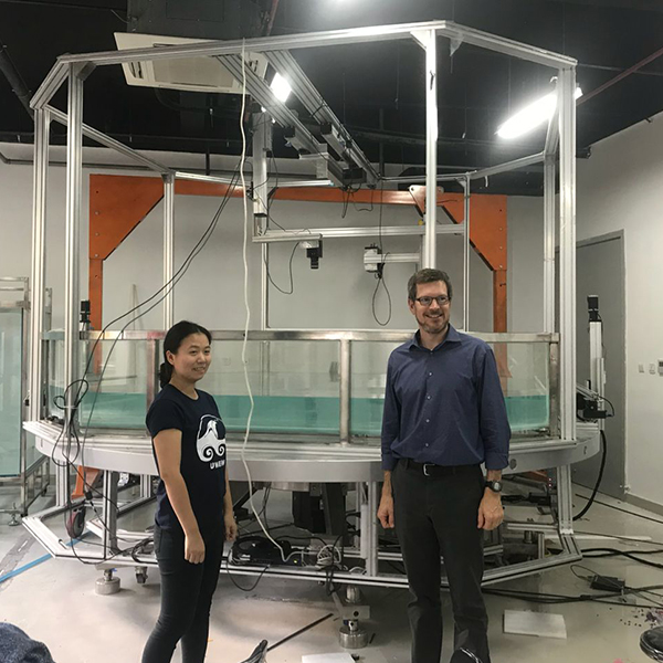
This preengineered multiaxis stage based on ServoBelt linear actuators is tested prior to adding it to a semiconductor-manufacturing machine. The stage has zero backlash, so the designer can tune the controls to dynamic requirements. That’s helpful because the only way to make fast index moves in this machine is to close the servoloops using the linear encoder, which requires a backlash-free driveline from motor to payload.
In contrast, a preengineered stage based on belt-driven drives is cost effective. It doesn’t need dual-loop control because it can get by with single-loop control using only the linear encoder. The drive also has inherently high mechanical damping, which lets the controls have high tuning gains (to four times the velocity and positional gains) for short settling times. In contrast, linear motors must simulate damping in the servoamplifier electronics, which reduces the possible positional gain.
Example: Rotary motion
Consider another application — a three-axis CNC desktop milling machine. These usually use linear-motion systems to position the cutting tool. In contrast, a preengineered stage combines rotary and linear positioning. Here, two belt-driven rotary devices carry loads on large-diameter rotary bearings and face each other. One carries a 150,000-rpm air-driven spindle. The other holds the workpiece and spins it 180° so that the cutting tool can reach any point on the workpiece’s surface in a 40 × 40 × 40-mm volume.
This CNC milling machine uses a preengineered stage that’s no more complex than it needs to be. The application needs good surface finish rather than positioning accuracy, so foregoes encoders and runs open loop (potentially saving thousands of dollars per machine).
A screw-driven linear actuator drives the linear axis but lets the rotary device with the cutting heads translate axially relative to the device holding the workpiece. All three devices move in sync. The linear axis handles Z-axis positioning and brings the cutting tool to the face of the workpiece.
The rotary design is stiff, which helps the design meet machining tolerances. A lubed-for-life option reduces the possibility of contamination, and effectors on both rotary stages extend through simple rotary seals in a wall of the cutting chamber. Seals protect inner workings from cutting fluid and flying ceramic dust. In contrast, X-Y-Z stages require bulky bellows and armadillo covers.
The rotary positioning of the cutting tool and workpiece uses polar coordinates, not Cartesian (as it typical for CNC kinematics). The controller takes in X-Y-Z G-code commands and converts them to polar coordinates in real time. The benefit? Rotary motion is better than linear for creating smooth surface finishes, because even the best linear bearings and ball screws “rumble” as the balls circulate in and out of a loaded state. This rumble reverberates through the motion system and can show up on parts as periodic surface-quality variations.
Post time: May-17-2021


