Linear motors are proliferating. They give machines the absolute highest precision and dynamic performance.
Linear motors are very quick and precise for positioning, but are also capable of slow, constant-traverse speed for machine heads and slides, as well as tool and part-handling systems. A variety of applications — laser surgery, vision inspection, and bottle and baggage handling — use linear motors because they are extremely reliable, require little maintenance, and improve production cycles.
Higher speed and force
Linear motors are directly coupled to their load, which eliminates a host of coupling components — mechanical couplings, pulleys, timing belts, ballscrews, chain drives, and rack and pinions, to name a few. This in turn reduces costs and even backlash. Linear motors also allow for consistent motion, precision positioning for hundreds of millions of cycles, and higher speeds.
Typical speeds attainable with linear motors vary: Pick and place machines (that make lots of short moves) and inspection equipment use linear steppers with speeds to 60 in./sec; flying-shear applications and pick and place machines that make longer moves use cog-free brushless linear motors for speeds to 200 in./sec; roller coasters, vehicle launchers, and people movers use linear ac induction motors to attain speeds to 2,000 in./sec.
Another factor that determines which linear-motor technology is best: Force required to move the application load. The load or mass along with the application’s acceleration profile ultimately determine this force.
Each application presents different challenges; however, in general, part-transfer systems use linear steppers with forces to 220 N or 50 lb; semiconductor, laser cutting, water-jet cutting, and robotics use brushless cog-free motors to 2,500 N; conveyor systems use linear ac induction motors to 2,200 N; and transfer line and machine tools use iron-core brushless motors to 14,000 N. Keep in mind that each application is different and manufacturer application engineers generally provide assistance at this specification step.
Other factors besides speed and force exist. For example, conveyor systems use linear ac induction motors because of their long length of travel, and the advantages of having a passive secondary without permanent magnets. Applications like laser eye surgery and semi-conductor fabrication use brushless cog-free for accuracy and smoothness of travel.
Basic operation
Linear motors operate through interaction of two electromagnet forces — the same basic interaction that produces torque in a rotary motor.
Imagine cutting a rotary motor and then flattening it out: This gives a rough idea of a linear motor’s geometry. Instead of coupling load to a rotating shaft for torque, load is connected to a flat moving car for linear movement and force. In short, torque is the expression of work that a rotary motor provides, whereas force is the expression of linear motor work.
Accuracy
Let us consider a traditional rotary stepper system first: Connected to a ballscrew with a pitch of 5 revolutions per inch, accuracy is approximately 0.004 to 0.008 in., or 0.1 to 0.2 mm. A rotary system powered by a servomotor is accurate to 0.001 to 0.0001 in.
In contrast, a linear motor coupled directly to its load gives accuracy ranging from 0.0007 to 0.000008 in. Note that coupling and ballscrew backlash are not included in these figures, and these further degrade the accuracy of rotary systems.
Relative accuracy varies: The typical rotary stepper we detail here can still position accurately to within the diameter of a human hair. That said, servos improve this by a factor of up to 80 times, while a linear motor can improve on this further — to 500 times smaller than the diameter of the human hair.
Sometimes maintenance and cost (over the life of the equipment) are more important considerations than accuracy. Linear motors excel here, too: Maintenance costs generally decrease with the use of linear motors, as noncontact parts enhance machine operation and increase mean time between failures. In addition, the zero backlash of linear motors eliminates shock, which further extends machine life. Other benefits: Time between maintenance cycles can be increased, allowing for more operational flow. Less maintenance and involved personnel improve the bottom line — profit — and reduce cost of ownership over the equipment life.
Benefits compared
Applications require linear movement. If using a rotary motor, then a mechanical conversion mechanism is necessary to convert the rotary to linear motion. Here, designers select the conversion mechanism most suitable to the application while minimizing limitations.
- Linear motor versus belt and pulley: To obtain linear motion from a rotary motor, a common approach is to use a belt and pulley. Typically, thrust force is limited by belt tensile strength; rapid starts and stops can cause belt stretching and therefore resonance, resulting in increased settling time. Mechanical windup, backlash, and belt stretching also lower repeatability, accuracy, and machine throughput. Because speed and repeatability are the name of the game in servo motion, this is not the best choice. Where a belt-pulley design can reach 3 m/sec, the linear can attain 10 m/sec. Without any backlash or windup, direct-drive linear motors further boost repeatability and accuracy.
- Linear motor versus rack and pinion: Rack and pinions provide more thrust and mechanical stiffness than belt-and-pulley designs. However, bidirectional wear over time leads to questionable repeatable and inaccuracies — this mechanism’s major drawbacks. Backlash prevents motor feedback from detecting actual load position, leading to instability — and forcing lower gains and slower overall performance.In contrast, machines powered by linear motors are faster and position more accurately.
- Linear motor versus ballscrew: The most common approach to convert rotary to linear motion is to use a lead or ballscrew. These are inexpensive but less efficient: Lead screws typically 50% or less, and ballscrews, about 90%. High friction produces heat, and long-term wear reduces accuracy. Travel distance is mechanically limited. In addition, linear speed limits can only be extended by increasing pitch, but this degrades positional resolution; overly high rotational speed can also cause screws to whip, resulting in vibration.Linear motors give long, unlimited travel. With an encoder at the load, long-term accuracy is typically ±5 µm/300 mm.
Basic linear motor types
As there are different rotary motor technologies, so too are there several linear motor types: stepper, brushless, and linear ac induction, among others. Note that linear technology utilizes drives (amplifiers) plus positioners (motion controllers) and feedback devices (such as Hall sensors and encoders) commonly available in industry.
Many designs benefit from custom linear motors, but stock designs are usually suitable.
Brushless iron-core linear motors are characterized by steel lamination in the moving forcer to channel magnetic flux. This motor type has higher force ratings and is more efficient, but weighs three to five times more than comparably sized cog-free motors. The stationary platen consists of multi-pole alternating polarity permanent magnets bonded on a nickel cold-rolled steel plate. The steel laminations on the moving forcer however react with the magnets on the stationary platen, which develop an “attractive” force and exhibit a small amount of cogging or ripple as the motor moves from one magnet field to another resulting in velocity variations.
These motors develop a large amount of peak force, have a greater thermal mass, and long thermal time constant — so are suitable for high-force, intermittent duty-cycle applications moving very heavy loads, as in transfer lines and machine tools; they are designed for unlimited travel and may include multiple moving platens with overlapping trajectories.
Brushless cog-free motors have a coil assembly in the moving forcer without steel laminations. The coil consists of wire, epoxy, and nonmagnetic support structure. This unit is much lighter in weight. The basic design produces a lesser amount of force, so additional magnets are inserted onto the stationary track (aid to increase force) and the track is U shaped with magnets on each side of this U. The forcer is inserted into the middle of the U.
These motors are suited for applications that require smooth operation without magnetic cogging, such as scanning or inspection equipment. Their higher accelerations are useful in semiconductor pick and place, chip sorting, and solder and adhesive dispensing. These motors are designed for unlimited travel.
Linear steppers have been available for a long time; the moving forcer consists of laminated steel cores precisely slotted with teeth, a single permanent magnet, and coils inserted into the laminated core. (Note that two coils result in a two-phase stepper.) This assembly is encapsulated in an aluminum housing.
The stationary platen consists of photochemically etched teeth on a steel bar, ground and nickel-plated. This can be stacked end-to-end for unlimited length. The motor comes complete with forcer, bearings, and platen. The attractive force from the magnet is used as a preload for the bearings; it also enables the unit to be operated in an inverted position for a variety of applications.
Ac induction motors consist of a forcer that is a coil assembly comprised of steel laminations and phase windings. The windings may be either single or three-phase. This allows for direct online control, or control through an inverter or vector drive. The stationary platen (called a reaction plate) usually consists of a thin layer of aluminum or copper bonded onto cold roll steel.
Once the forcer coil is energized, it interacts with the reaction plate and moves. Higher speeds and unlimited travel lengths are this design’s strengths; they’re used for material handling, people movers, conveyors, and sliding gates.
New design concepts
Some of the latest design improvements have been implemented via reengineering. For example, some linear stepper motors (originally designed to provide motion in one plane) are now reengineered to provide motion in two planes — for X-Y motion. Here, the moving forcer consists of two linear steppers mounted orthogonally at 90° so that one provides X-axis motion, and the other provides Y-axis motion. Multiple forcers with overlapping trajectories are also possible.
In these two-plane motors, the stationary platform (or platen) utilizes new composite construction for strength. Stiffness is also improved, so deflection is reduced by 60 to 80% compared to previous production models. Platen flatness exceeds 14 microns per 300 mm for accurate movement. Finally: Because steppers have a natural attractive force, this concept allows the platen to be mounted either face up or inverted, thus providing versatility and flexibility for applications.
Another engineering innovation — water cooling — extends the force capability of linear ac induction motors by 25%. With this capability extension, as well as the benefit of unlimited travel length, ac induction motors provide highest performance for many applications: amusement rides, baggage handling, and people movers. Speed is variable (from 6 to 2,000 in./sec) through adjustable speed drives presently available in industry.
Yet another motor includes a stationary cylindrical housing with a linear moving part to provide motion. The moving part may be a rod consisting of copper-clad steel, a moving coil, or a moving magnet, like a piston within a cylinder.
These designs provide the benefits of linear motor plus perform similar to a linear actuator. Applications include biomedical colonoscopies, cameras with long shutter actuators, telescopes that require vibration damping, lithography focusing motors, generator switch gears that throw breakers to put generators online, and food pressing — as when stamping out tortillas.
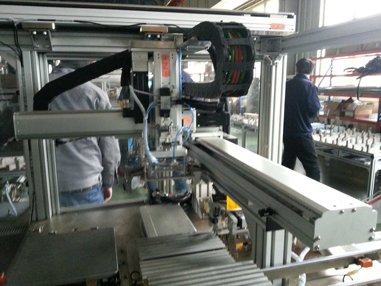
Complete linear motor packages or stages are suitable for positioning payloads. These consist of motor, feedback encoder, limit switches, and cable carrier. It is possible to stack stages for multi-axis movement.
One advantage of linear stages is their lower profile, which allows them to fit into smaller spaces compared with conventional positioners. Fewer components make for increased reliability. Here, the motor is connected to regular drives. In a closed-loop operation, the position loop is closed with a motion controller.
Again, besides stock products, custom and specialty designs abound. In the end, it’s best to review equipment needs with an application engineer to determine the optimum linear product suited for application needs.
Post time: Jul-22-2021


