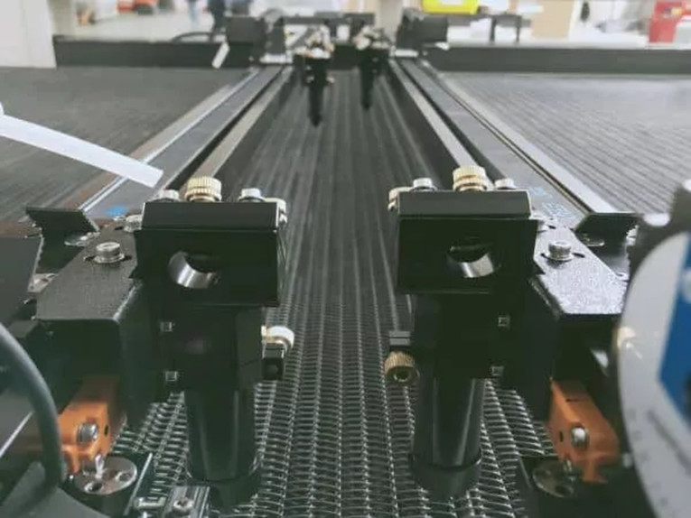
More on the geometry of dual guide rails.
Linear guide systems include guide rails,slides and ways. Industry categorizes them into a few basic types as well — including profile rails, drawer slides, linear bearings, guide wheels and plain bearings. A typical arrangement includes a rail or shaft, and carriages and runner blocks. They can also be distinguished by the method of contact, either sliding or rolling.
A major function of rolling guides is to reduce friction in machines. They’re used in various applications ranging from advanced semiconductor manufacturing devices to large machine tools and construction equipment.
Semiconductor manufacturing equipment or inspection apparatus that requires high precision positioning is a good application for linear guides. In the case of a machine tool for cutting, linear guides are used instead of sliding-contact linear-motion bearings to cope with temperature rise and durability issues associated with ever-increasing feed speeds.
The classic application for profile rails is in the machine tool industry where load capacity, stiffness and accuracy are paramount. In medical equipment such as CAT scan, MRI and x-ray machines, square rails are more common.
On the other hand, round rails can offer several advantages, one of which is the ability to run smoothly when mounted to less than perfect surfaces—defined as having a flatness error of over 150 μm/m.
For cleanroom and food-processing applications that can’t tolerate contamination, linear guides that use rolling elements (as well as plain bearing systems) are unsuitable because of their need for lubrication requirements.
Some applications demanding extremely high precision and accuracy use fluid-floated bearings for the highest accuracy and precision possible. These are hydrostatic or aerostatic bearings using a highpressure fluid between the rail and carriage. They’re more expensive and harder to manufacture than other linear options but get top precision and accuracy.
Important considerations for choosing a linear-motion rolling guide include the loading (both static as well as applied), the stroke and speed, as well as the desired precision and accuracy and the required life. Preloading is sometimes needed as well depending on application requirements. Lubrication is another important consideration, as is any method to minimize contamination of the linear guide system from environmental factors such as dust and other contaminants using bellows or special seals.
Linear guide rails and bearings offer high stiffness and good travel accuracy. They can support not only downward, upward, and side loads, they can also withstand overhung, or moment loads. Of course, the larger the linear rail and bearing system, the more moment capacity it has, but the arrangement of the bearing raceways — face-to-face or back-to-back — also influences the amount of overhung load that it can support.
While the face-to-face design (also known as the X arrangement) provides equal load capacities in all directions, it results in a shorter moment arm along which overhung loads are applied, which reduces moment load capacity. The back-to-back arrangement (also known as the O arrangement) provides a larger moment arm and gives higher moment load capacities.
But even with the back-to-back arrangement, linear guides have a relatively short distance between the raceways (essentially equal to the width of the rail) which limits their ability to handle roll moments, which are caused by loads overhung in the Y direction. To counter this limitation, using two rails in parallel — with either one or two bearings on each rail — allows the roll moment to be resolved into forces on each bearing block. Because linear bearings have much higher capacity for forces than for moments (especially roll moments), bearing life can be significantly increased. Another benefit of using dual guide rails and allowing moments to be resolved into forces is that linear bearings generally deflect less under pure forces than under moment loads.
Many linear actuator designs include two rails in parallel with the drive mechanism — belt, screw, or linear motor — incorporated between the rails. While it’s not imperative that the drive be centered between the guide rails, doing so helps ensure even loading on all of the bearings, and reduces cogging, or uneven drive forces on each rail and bearing set. This arrangement also reduces the height of the actuator, making it relatively compact given the high load and moment capacity provided by the dual guide rails.
Post time: Apr-11-2022


