High moment loads can dictate the use of a dual-rail style linear actuator.
Selecting an actuator based on approximations of the performance requirements is arguably more risky than choosing a linear guide or drive with minimal application info. But still, the situation is quite common where a designer or engineer needs a reasonable estimate of the system that will work best for their application, before all the application criteria are nailed down.
Although a proper sizing exercise requires a thorough understanding of the application requirements, a general solution—suitable for initial design and costing estimates—can usually be established based on four key criteria.
Load
The load that needs to be carried, and its orientation relative to the system, is one of the most important criteria in choosing a linear actuator. Light loads that are mounted more-or-less directly over the bearings can be accommodated by virtually any guide technology—recirculating profiled rail bearings, linear bushings and shafts, or even plain bearings. However, the heavier the load, and the more moment (pitch, roll, and/or yaw) that it creates, the more robust the guide mechanism should be in order to ensure suitable life and minimal deflection.
Accuracy
Understanding the requirements for positioning accuracy and repeatability will help to narrow the decision regarding drive mechanism. Low-accuracy, point-to-point positioning can be accomplished with a pneumatic drive or belt and pulley system, while positioning accuracy and repeatability in the single-micron range would require a ball screw or even a linear motor. Although the load can often be accommodated by any of several drive technologies, repeatability is often the deciding factor between these options.
Speed
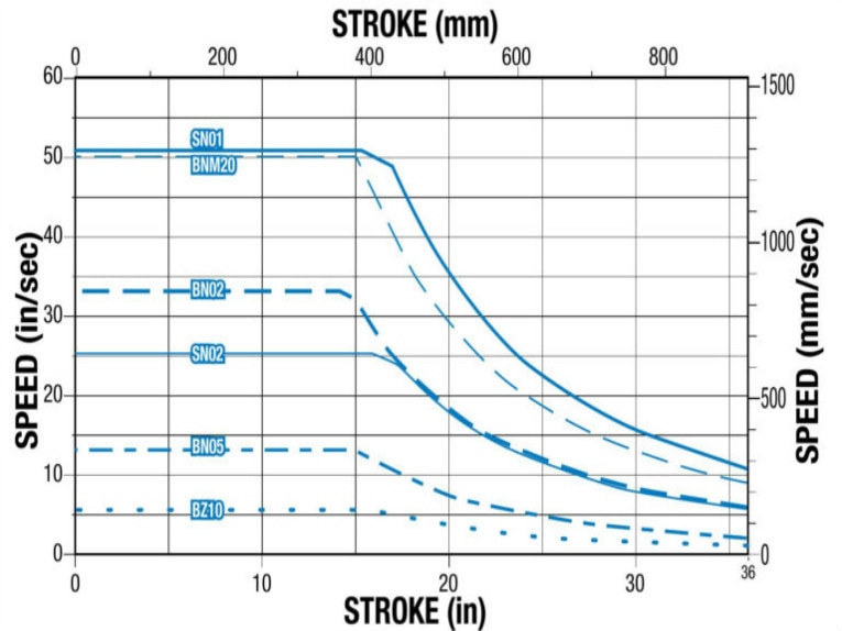
The average and maximum velocities during the move will also help define the choice of drive mechanism. For example, a rule of thumb is that maximum speed for ball screw assemblies is 1 m/s, although there are ways to obtain faster speeds. Belts, on the other hand, can easily travel up to 10 m/s, and maximum speed for linear motor drives is primarily limited by the supporting guide mechanism. Acceleration also plays a role, both in drive and guide selection.
Travel
While the required travel is less often a make-or-break criteria, it’s important to double-check that the chosen linear actuator type can meet the specification for stroke length. Ball and lead screws in particular have limited travel ranges. Again, a rule of thumb for screw drives is 3 meters maximum length. Although screws are available in longer lengths, as length increases, maximum speed decreases, due to the critical speed of the screw.
Post time: Jul-06-2020


